- 您现在的位置:买卖IC网 > Sheet目录341 > MAX8790AETP+T (Maxim Integrated)IC LED DRVR WHITE BCKLGT 20-TQFN
�� �
�
�Six-String� White� LED� Driver� with� Active�
�Current� Balancing� for� LCD� Panel� Applications�
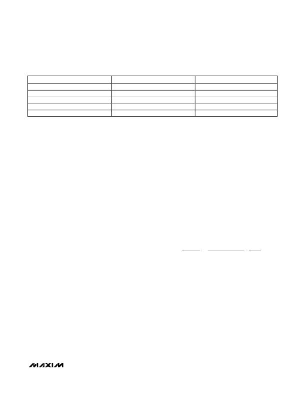
�Table� 4.� Component� Suppliers�
�Murata�
�Nichia�
�Sumida�
�Toshiba�
�Vishay�
�SUPPLIER�
�PHONE�
�770-436-1300�
�248-352-6575�
�847-545-6700�
�949-455-2000�
�203-268-6261�
�WEBSITE�
�www.murata.com�
�www.nichia.com�
�www.sumida.com�
�www.toshiba.com/taec�
�www.vishay.com�
�?� V� IN� _� MIN� ?� ?� V� OUT� IN� _� MIN� ?� ?� η� TYP� ?�
�?� V�
�L� =� ?� ?� ?� ?� ?� ?�
�(� V� OUT� (� MAX� )� +� V� DIODE� ?� 2� � V� IN� (� MIN� )� )� � R� S�
�51� mV� � f� OSC� (� MIN� )�
�Inductor Selection�
�The� inductance,� peak� current� rating,� series� resistance,�
�and� physical� size� should� all� be� considered� when�
�selecting� an� inductor.� These� factors� affect� the� conver-�
�ter’s� operating� mode,� efficiency,� maximum� output� load�
�capability,� transient� response� time,� output� voltage� ripple,�
�and� cost.�
�The� maximum� output� current,� input� voltage,� output� volt-�
�age,� and� switching� frequency� determine� the� inductor�
�value.� Very� high� inductance� minimizes� the� current� rip-�
�ple,� and� therefore� reduces� the� peak� current,� which�
�decreases� core� losses� in� the� inductor� and� I� 2� R� losses� in�
�the� entire� power� path.� However,� large� inductor� values�
�also� require� more� energy� storage� and� more� turns� of�
�wire,� which� increases� physical� size� and� I� 2� R� copper� loss-�
�es� in� the� inductor.� Low� inductor� values� decrease� the�
�physical� size,� but� increase� the� current� ripple� and� peak�
�current.� Finding� the� best� inductor� involves� the� compro-�
�mises� among� circuit� efficiency,� inductor� size,� and� cost.�
�When� choosing� an� inductor,� the� first� step� is� to� deter-�
�mine� the� operating� mode:� continuous� conduction� mode�
�(CCM)� or� discontinuous� conduction� mode� (DCM).� The�
�MAX8790A� has� a� fixed� internal� slope� compensation,�
�which� requires� a� minimum� inductor� value.� When� CCM�
�mode� is� chosen,� the� ripple� current� and� the� peak� cur-�
�rent� of� the� inductor� can� be� minimized.� If� a� small-size�
�inductor� is� required,� DCM� mode� can� be� chosen.� In�
�DCM� mode,� the� inductor� value� and� size� can� be� mini-�
�mized� but� the� inductor� ripple� current� and� peak� current�
�are� higher� than� those� in� CCM.� The� controller� can� be�
�stable,� independent� of� the� internal� slope� compensation�
�mode,� but� there� is� a� maximum� inductor� value� require-�
�ment� to� ensure� the� DCM� operating� mode.�
�The� equations� used� here� include� a� constant� LIR,� which�
�is� the� ratio� of� the� inductor� peak-to-peak� ripple� current�
�to� the� average� DC� inductor� current� at� the� full-load� cur-�
�rent.� The� controller� operates� in� DCM� mode� when� LIR� is�
�higher� than� 2.0,� and� it� switches� to� CCM� mode� when� LIR�
�core� material� and� ratio� of� inductor� resistance� to� other�
�power-path� resistances,� the� best� LIR� can� shift� up� or�
�down.� If� the� inductor� resistance� is� relatively� high,� more�
�ripple� can� be� accepted� to� reduce� the� number� of�
�required� turns� and� increase� the� wire� diameter.� If� the�
�inductor� resistance� is� relatively� low,� increasing� induc-�
�tance� to� lower� the� peak� current� can� reduce� losses�
�throughout� the� power� path.� If� extremely� thin� high-resis-�
�tance� inductors� are� used,� as� is� common� for� LCD� panel�
�applications,� LIR� higher� than� 2.0� can� be� chosen� for�
�DCM� operating� mode.�
�Once� a� physical� inductor� is� chosen,� higher� and� lower�
�values� of� the� inductor� should� be� evaluated� for� efficiency�
�improvements� in� typical� operating� regions.� The� detail�
�design� procedure� can� be� described� as� follows:�
�Calculate� the� approximate� inductor� value� using� the� typ-�
�ical� input� voltage� (V� IN� ),� the� maximum� output� current�
�(I� OUT(MAX)� ),� the� expected� efficiency� (� η� TYP� )� taken� from�
�an� appropriate� curve� in� the� Typical� Operating�
�Characteristics,� and� an� estimate� of� LIR� based� on� the�
�above� discussion:�
�2�
�?� V� OUT� ?� ?� I� OUT� (� MAX� )� � f� OSC� ?� ?� LIR� ?�
�The� MAX8790A� has� a� minimum� inductor� value� limitation�
�for� stable� operation� in� CCM� mode� at� low� input� voltage�
�because� of� the� internal� fixed� slope� compensation.� The�
�minimum� inductor� value� for� stability� is� calculated� by� the�
�following� equation:�
�L� CCM� (� MIN� )� =�
�where� 51mV� is� a� scale� factor� based� on� slope� compen-�
�sation,� and� R� S� is� the� current-sense� resistor.� To� deter-�
�mine� the� minimum� inductor� value,� the� R� S� can� be�
�temporarily� calculated� using� the� following� equation:�
�is� lower� than� 2.0.� The� best� trade-off� between� inductor�
�size� and� converter� efficiency� for� step-up� regulators�
�generally� has� an� LIR� between� 0.3� and� 0.5.� However,�
�R� S� _� TMP� =�
�100� mV�
�,�
�1� .� 2� � I� IN� (� DCMAX� )�
�depending� on� the� AC� characteristics� of� the� inductor�
�where� 100mV� is� the� current-limit� sense� voltage.�
�______________________________________________________________________________________�
�17�
�发布紧急采购,3分钟左右您将得到回复。
相关PDF资料
MAX8790ETP+T
IC LED DRVR WHITE BCKLGT 20-TQFN
MAX8791GTA+
IC MOSFET DRIVER 8-TQFN
MAX8811EEE+
IC DRVR DL PHASE HS 16-QSOP
MAX8821ETI+
IC LED DRVR WHITE BCKLGT 28-TQFN
MAX8822ETE+T
IC LED DRVR WHITE BCKLGT 16-TQFN
MAX8830EWE+T
IC LED DRVR WHITE BCKLGT 16-UCSP
MAX8831EWE+T
IC LED DRIVR WHITE BCKLGT 16-WLP
MAX8834ZEWP+T
IC LED DRIVR BCKLGT FLASH 20-WLP
相关代理商/技术参数
MAX8790AETP+X01
功能描述:LED照明驱动器 Six-String White LED Driver RoHS:否 制造商:STMicroelectronics 输入电压:11.5 V to 23 V 工作频率: 最大电源电流:1.7 mA 输出电流: 最大工作温度: 安装风格:SMD/SMT 封装 / 箱体:SO-16N
MAX8790AEVKIT+
功能描述:LED 照明开发工具 MAX8790A Eval Kit RoHS:否 制造商:Fairchild Semiconductor 产品:Evaluation Kits 用于:FL7732 核心: 电源电压:120V 系列: 封装:
MAX8790ETP+
功能描述:LED照明驱动器 Six-String White LED Driver RoHS:否 制造商:STMicroelectronics 输入电压:11.5 V to 23 V 工作频率: 最大电源电流:1.7 mA 输出电流: 最大工作温度: 安装风格:SMD/SMT 封装 / 箱体:SO-16N
MAX8790ETP+T
功能描述:LED照明驱动器 Six-String White LED Driver RoHS:否 制造商:STMicroelectronics 输入电压:11.5 V to 23 V 工作频率: 最大电源电流:1.7 mA 输出电流: 最大工作温度: 安装风格:SMD/SMT 封装 / 箱体:SO-16N
MAX8790EVKIT+
功能描述:LED 照明开发工具
RoHS:否 制造商:Fairchild Semiconductor 产品:Evaluation Kits 用于:FL7732 核心: 电源电压:120V 系列: 封装:
MAX8791AGTA+
制造商:Rochester Electronics LLC 功能描述: 制造商:Maxim Integrated Products 功能描述:
MAX8791AGTA+T
制造商:Rochester Electronics LLC 功能描述: 制造商:Maxim Integrated Products 功能描述:
MAX8791BGTA+
功能描述:功率驱动器IC Single-Phase Synch MOSFET Driver RoHS:否 制造商:Micrel 产品:MOSFET Gate Drivers 类型:Low Cost High or Low Side MOSFET Driver 上升时间: 下降时间: 电源电压-最大:30 V 电源电压-最小:2.75 V 电源电流: 最大功率耗散: 最大工作温度:+ 85 C 安装风格:SMD/SMT 封装 / 箱体:SOIC-8 封装:Tube